Zero Path Continuation Method Matlab Code
Introduction to Matlab zero padding
In time series domain frequency resolution is depends on no of points present in the signal; therefore, we always need to add points in the signal; if the signal is in the same domain, then it's easy to add new points, but if we are working on real-time data then it's difficult to add new points. Mostly if data is already stored in the system and we are working offline, then we cannot deal with new data points. Therefore to improve frequency resolution, zero paddings are used. Zero padding means adding simply zeros at the end of the input signal. In this topic, we are going to learn about Matlab zero padding.
Syntax
Signal 2 = [signal1 zeros (1,3)] Output signal name = [ input signal name zeros (no of rows ,no of columns)]
How to perform zero paddings in Matlab?
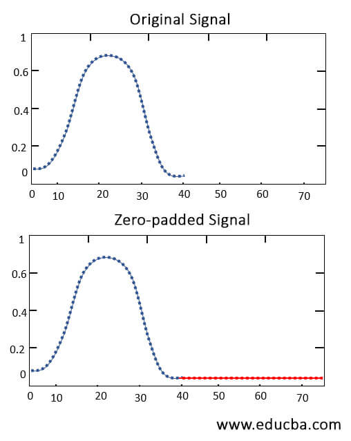
Zero padding means adding zeros at the end of the input signal. When we add extra information to any signal, then the characteristics and response of the signal may changes. But we are adding zeros in a signal that means; ideally, we are not adding any extra information; therefore, the characteristics and response of the signal will remain constant. It will only increase the frequency resolution of the signal in Fourier transform. In figure 1, there are two signals first signal is the original input signal, and the second signal is a zero-padded signal. In first signal frequency response is from zero to forty only. And in second signal frequency response is from zero to eighty points, which is almost double of an input signal. In the figure, black color indicates original input points, and red color indicates new zero-padded point.
Examples
Here are the following examples mention below
Example #1
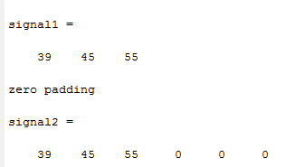
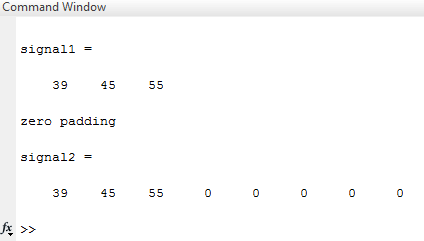
Let us consider one simple example; in this example, two variables are used to represent input signal and output signal. An input signal is represented by signal 1, an output signal is represented by signal 2.input signal is a one-dimensional array of three elements [39 45 55]. after initializing the input signal, a zeros command is applied to the input signal with parameters (1,3). Here (1,3) represents one row and three columns that means three zeros will be added at the end of the input signal, which is illustrated in example 1(a). Similarly, in Example 1(b), the same signal is used as an input signal, and the zeros command is applied to the signal. Still, parameters are different from the previous example .here parameters passed. However, the function is (1,5), (1,5) represents one row and five columns that means five zeros will be added at the end of the signal. Initially, there are three data points in the first signal, and after zero paddings, there will be a total of eight data points present the output signal, which is illustrated in example 1 (b).
Matlab program for Example 1(a) –
clc ;
              clear all ;
              signal1 = [ 39 45 55] disp ('zero padding')
              signal2 = [ signal1 zeros (1, 3)]
Output ( Command window) –
Matlab program for Example 1(b) –
clc ;
              clear all ;
              signal1 = [ 39 45 55] disp ('zero padding')
              signal2 = [ signal1 zeros(1, 5)]
Output (command window) –
Example #2
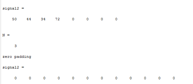
In this example, two variables are used to represent input signal and output signal. The input signal is represented by signal 1, and the output signal is represented by signal 2.input signal is a one-dimensional array of four elements [50 44 34 72]. after initializing the input signal, we have applied the zeros function on a signal with parameters (1,4); just like the previous example, it will simply add four zeros at the end of the input signal. Mostly this zero padding concept is used to maintain the length of the signal in Fourier transform. Therefore we have assigned one variable, 'N', which represents the length of the signal. In example 2(a), instead of direct values, one function is passed through the zeros command, which is the N * length of the input signal. It will give output as 4 * 3, which is 12, so twelve zeros will be added in input. This example is illustrated in Example 2(a).
Matlab program for Example 2(a) –
clc ;
              clear all ;
              close all ;
              signal1 = [50 44 34 72] signal2 = [signal1 zeros(1, 4)] N = 3
              disp ('zero padding')
              signal2 = zeros(1, N*length(signal1))
Output (Command window ) –
Example 2(b)
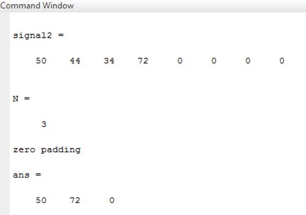
In this example, we have used the same input signal [50 44 34 72], which has four data points .signal1 is the input signal and signal 2 is the output signal. Zeros function is applied on input signal with parameters (1,4), which means four zeros will be added to the signal. But if we want the selected portion only as output, then we can do slicing. Therefore we will get output from the first data point to the last data point by command signal:N: end, which is illustrated in example 2(b).
Matlab program for Example 2(b) –
clc ;
              clear all ;
              close all ;
              signal1 = [50 44 34 72] signal2 = [signal1 zeros(1, 4)] N = 3
              disp ('zero padding')
              signal 2 ([1:N:end])
Output ( Command window ) –
Example 2©
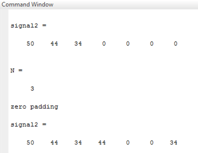
In this, we have used the same input signal, which has four data points. By using the zeros function first, we have padded input signal by dimension one in to eight( one row and eight columns). After creating the output signal, we match the dimensions of the input and output signal; therefore, we get some data at output.
Matlab program for Example 2© –
clc ;
              clear all ;
              close all ;
              signal1 = [50 44 34 ] signal2 = [signal1 zeros(1,4)] N = 3
              disp('zero padding')
              signal2([1:N:end]) = signal1
Output ( Command window) –
Conclusion
In this article, we have seen various ways to add zeros to any signal. Zeros command is used to padd data to any signal. By using this function, we can increase frequency resolution .this function increases frequency resolution but never changes any other characteristics.
Recommended Articles
This is a guide to Matlab zero padding. Here we discuss the various ways to add zeros in any signal and how zero commands are used to padd data to any signal. You may also have a look at the following articles to learn more –
- uigetfile Matlab
- Matlab gca
- Bisection Method Matlab
- Matlab Global Variables
ackermannprall2001.blogspot.com
Source: https://www.educba.com/matlab-zero-padding/